
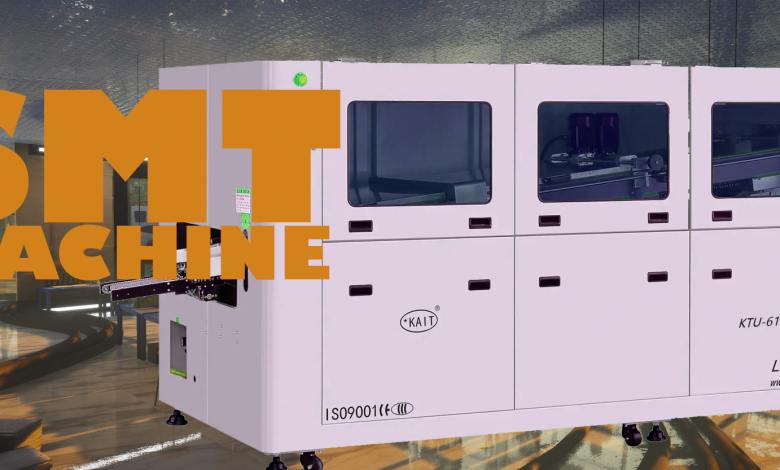
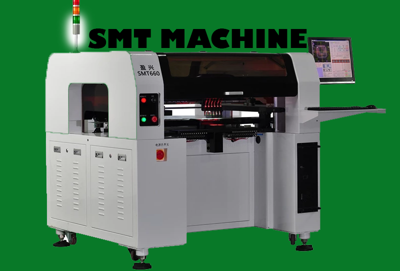
SMT Machine
Standard technology in electronics circuit assembly is Surface Mount Technology (SMT). In recent years, many PCB manufacturers have relied on SMT technology to manufacture their boards. Electronic components can be mounted to surfaces of PCBs using Surface Mount Technology. Plating through-hole technology is different from Surface Mount Technology, and Surface Mount Technology is the best alternative. SMT simplifies the process of building even the most complex electronic circuit boards.
The technology can be used to make smaller assemblies that are highly repeatable. With Surface Mount Technology, we can achieve a high degree of automation and precision. Surface Mount Technology requires very little assembly time. The SMT process consists of simply picking and placing PCB components onto the board.
How do SMT electronics work?
Electronics are manufactured with surface-mount technology (SMT) by automating placing electronic components on a board PCB (Printed Circuit Board).
An SMT component is positioned directly on the surface of the PCB as opposed to being soldered to a wire lead, as in conventional through-hole technology (THT). Electronic assemblies are most commonly assembled using SMT. In addition to placing and soldering components to the PCB, electronic assembly involves the following steps:
1. Installing soldering paste
During the SMT assembly process, soldering paste is applied for the first time. The silk-screen method is used to apply the solder paste to the boards. It is necessary to use either stainless-steel stencils to “print” the paste onto the board, or product-specific pastes, depending on the board’s design. The soldering paste is applied only to the soldering points using a stainless-steel stencil custom cut for the project.
Several inspections are performed to ensure the soldering paste has been applied evenly and correctly after the paste has been applied. Factual accuracy has been achieved using the soldering paste before the boards are transferred to the SMT assembly line.
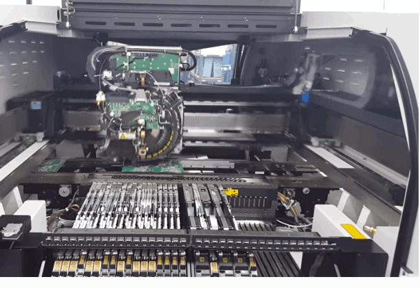
2. Assembly and component placement
In the SMT machine, the required electronic components are loaded into trays or reels. Intelligent software systems prevent inadvertent switching or misleading components during loading. Using preprogrammed X-Y coordinates, a vacuum pipette automatically removes each element from its reel or tray and automatically places it on the board in its proper position. Assembly machines can assemble as many as 25,000 parts per hour. In the reflow ovens, the soldered components are attached to the board after SMT assembly has been completed.
3. Soldering of components
There are two main methods we use for soldering electronic components, each of which has distinct advantages in quantity. Series production orders are completed using reflow-soldering. A nitrogen atmosphere is applied to boards, and air is gradually heated until the solder paste melts and the flux vaporizes, fusing the components to the PCB. The panels are then cooled. SMT assembly is completed when the tin in the soldering paste dries and hardens.
We have a vapor-phase soldering process that is suitable for prototypes and sensitive components. Solder paste is melted at its specific melting point (Golden) by heating boards in this manner. By analyzing their soldering temperature profiles, we can solder components at different temperatures based on the temperature profiles of their SMT components.
4. An AOI and a visual check
Assembling SMT components is completed by soldering. A visual inspection of assembled boards is done for almost every line production order to ensure quality or catch and correct errors.
Each panel is automatically inspected using several cameras which compare the board’s appearance with a predefined, accurate reference image. A commission is pulled from the machine and checked for further inspection if there are any deviations.
The machine operator is then informed of any potential issues. In the production process of SMT assembly, the AOI visual check ensures consistency and accuracy.
Advantages
The main advantages of SMT over the older through-hole technique are:
Reduced component size. Component density is much higher (plenty of components per unit area) and connection density per component.
It is possible to place components on both sides of the circuit board.
Higher connections density since the holes doesn’t block routing space on inner or backside layers if components are mounted only on one side.
When components are positioned incorrectly, the molten solder will align them with solder pads due to surface tension. (On the other hand, through-hole parts can be slightly misaligned through the fact that, once the leads are inside the holes, the components are fully aligned and cannot move laterally.)
Improved mechanical performance when subjected to shock and vibration (partly due to lower mass, but also due to less cantilevering)
There are less inductance and resistance at the connection; therefore, there are fewer unwanted RF signal effects and better performance at high frequencies.
The smaller package area (, the smaller loop area) and lower lead inductance mean better EMC performance (lower radiated emissions).
Drilling fewer holes is easier. (Drilling PCBs is exhausting and expensive.)
Automation of equipment reduces initial cost and sets up a time for mass production.
Faster and simpler automated assembly. More than 136,000 components can be placed per hour with some placement machines.
SMT components can be cheaper than through-hole equivalents.
Disadvantages
SMT may not be suitable for components subjected to repetitive mechanical stress, such as connectors that interface with external devices that are frequently connected and disconnected.
Solder connections on SMDs may be damaged by the thermal cycling of potting compounds.
The installation of many types of SMT component packages in sockets is impossible, making it easy to replace or modify a circuit and to replace failed components. (Virtually all parts with through-holes can be socketed.)
SMT solder joint sizes are rapidly shrinking as ultra-fine pitch technology is developed. As the amount of solder in each joint continues to decrease, reliability becomes more of a concern. Solder joints commonly suffer from voiding when reflowing solder paste when used for SMT applications. Joints with voids may become weaker and eventually fail.
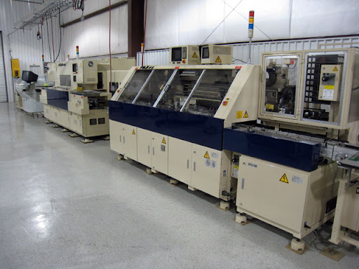
Application of SMT Machines
In today’s world, surface mount technology is widely used to produce nearly all electronics circuits. Surface Mount Technology can be used for mounting almost all electrical components on a PCB.
Electronic components can be packed onto a PCB in smaller spaces using this technology. It is a technology that will continue to grow in the years because it is not going away anytime soon. Using this technology is the best way to go if you are a printed circuit board assembler. SMT is one of the most beneficial technologies, even though it is more expensive.
Several advantages come with SMT. Manufacturing with SMT is cost-effective and time-saving. Electrical components can be positioned on both sides of the board when using SMT. Another application of SMT technology is the lower setup and manufacturing costs.
Conclusion
Thank you for taking the time to read our article. With SMT machines, work becomes more accessible, costs are reduced, and production capacity is increased. Knowing how SMT machines work, the different types, how they are programmed, and their qualities are essential before purchasing one.
FAQs
At present, there are more than 40 thousand kinds of components. There are 698 types of essential components and over 40 thousand extended components.
The basics are parts like chip resistors and chip capacitors that are frequently used. The P&P machines are already loaded with them, so there is no need for the operator to move them around, which results in fewer labor costs.
Parts from the Extended Components Library require manual mounting of the feeders, increasing labor costs. Each extended component costs $3.
PCB production requires a Gerber file.
Files such as BOMs (Bills of Materials).
Using our automated SMT assembly machines to locate each part on the board, our CPL file (Component Placement List / Pick & Place File (PNP)) decides which features will be placed on the board.
Upload your Gerber files –Add your BOM/CPL files — Select parts you want to be assembled — Get a quote.